 Photos by David Tisherman
Great projects always start with visuals based on true design discipline, says master designer/builder David Tisherman. Bringing superior visual schemes to fruition, however, also requires artisan skill during the construction phase. In this second installment covering a challenging residential project, Tisherman discusses specific measures needed to create work that is not only beautiful but will stand the test of time.
The project we began discussing last month is a perfect example of "custom" work. It's located on a hillside lot with a thrilling ocean view, and the clients wanted something befitting the setting. It also came with a set of nasty challenges that could almost make your head spin.
In the first part of this profile, I described the site-preparation process, which meant addressing a variety of code requirements, horrific soils conditions and a complete lack of access for equipment and materials.
 Figure 1
In fact, for the project as a whole, the design, engineering and construction were precise responses to a unique situation, anything short of that would be to invite disaster. Meaning, this kind of work is no place for generic plans, or practicing. I argue that all projects, be they so-called "high-end" or for more middle-class clients, require site-specific engineering. Reason being, the soils determine the structural design of the pool and ultimately the price. That's why, to my mind, there should be no such thing as a "cookie-cutter" pool.
And, before we jump into the process, this is what I find so exciting about creating aquatic spaces on this level: making great art means understanding design combined with knowing how to solve problems. Every project, every site and every client are different – and that's what makes what we do so potentially special, and sometimes rather colossal.
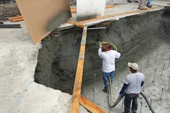 Figure 2
Dug In
To briefly recap, we've skinned the landscape, removed the stone surface from the concrete deck, removed the existing pool shell and have established the new shape in dimensions staying mostly within the footprint of the original pool. We've also done extensive soils testing and structural engineering to accommodate the horrible geological conditions. As a result, we've over-excavated part of the pool floor down to competent soil.
Now, we're ready to start building the new pool.
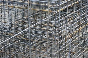
We began with a mat of steel, meaning steel installed in a horizontal grid. (Mats run horizontally and curtains are vertical.) In this case, we are raising the floor, building a foundation of solid concrete to give us a full area to work with. The mats are tied together with vertical bars, building up layers, #18 rebar on 18 inches all three ways – both directions horizontally and vertically.
 Figure 3
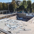
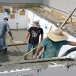
In this project, the soils were so bad that we found that as we walked on the deck around the perimeter, the dirt kept falling in on our work, making the process almost impossible (Figure 1). To solve the problem we "flashed" a thin layer of 3,000-psi shotcrete onto the walls strictly to hold the soil in place (Figure 2). (It's important to note this is not structural concrete in any way, just something to hold the earth back from caving in.)
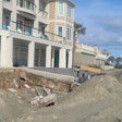
With that problem solved, we began building the pool in earnest, finishing the steel for the floor mats, the bond beam, steps, benches and the spa structure. Everything was measured and re-measured, ensuring all of the dimensions were plumb, level and square (Figure 3).
I give huge credit to Jim Pope of Mission Steel, who is the best steel installer I've ever seen and who always does a masterful job creating wildly complex structures.
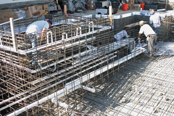 Figure 4
Plumbed To Perfection
As the steel was nearing completion, we strategically left out pieces to provide access for the plumbing lines (Figure 4). That process required a fair amount of careful coordination between Pope's crew and the plumber, Poncho Rodriguez of Coast to Coast Plumbing, another artisan who I regard as the best of the best and take with me on projects all over the country. (I mention Pope and Rodriguez here to make a point: When you strive for perfection, you have to have a team you trust, people you know have the skill, patience and focus to get it right every single time.)
Like every other aspect of the project, the hydraulic system is precisely calculated to deliver return and suction flow rates that are well below industry standards, which drives energy efficiency, service life of the equipment and contributes to safety. That process is fairly straightforward if you follow basic calculations for flow requirements and are wary of basic measures, such as making sure your pumps are pushing water, rather than pulling it, which can lead to problems with prime.
These days, we hear a great deal about VGB requirements and without going into detail, I'm proud to say that my pools have been compliant since long before that law was written. All the drains are split and spaced so that entrapment is virtually impossible and suction velocities are well below the standard.
In this project, one of the trickier elements was the use of "Tishways" in the dam wall of the spa. The clients wanted an alternative to the standard flat weir configuration typical of most pool-and-spa combinations. Years ago I developed this detail where rivulets of water create a delicate water-in-transit effect, providing a more elegant visual along with a delicate sound. (I'll cover this detail in the next installment of this series.)
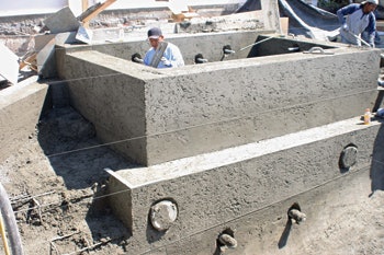 Figure 5
Also, with so much plumbing and steel, it's especially important to maintain proper spacing so that when the concrete is shot, you achieve proper coverage around all the pipes and bars. Everything has to be firmly tied into place so there is no vibration or "shadowing" in unwanted spaces in the concrete.
In terms of spacing, I'm always looking for at least three inches of coverage around plumbing and steel. This is one of the reasons I create wide dam walls. It's very difficult to put 3-inch plumbing in 9-inch wall or even a 12-inch wall unless it's a perfect straight line.
This brings up an extremely important point: I always start with the visual details and make the construction work to meet the desired effect, not the other way around. Clients don't care what size steel is in the dam wall, but instead are concerned with the appearance of the end product. In a case like this, the width of the wall fits the visual design in terms of proportion and scale.
Shot Into Place
On all of my jobs, I employ a deputy inspector to double check the work during the placement of shotcrete. If the excavation, steel or plumbing isn't in perfect place and correctly installed we have a problem. The idea is to be certain, beyond any level of doubt, that everything to the finest detail is per the plan details and compliant with all building codes. Once the concrete is in place, there's no turning back, at least not without massive expense, so it is crucial that you know the work is flawless.
Work at this level requires careful verification of the plans and the ability to make adjustments when things aren't working visually. In other words, designers need to understand construction and the builder needs to understand design so that adjustments can be made during the process.
 Figure 6
When it comes to the concrete, I am a firm believer in the shotcrete process because it can be far more precisely controlled in terms of the mix schedule. I follow the American Concrete Institute standards and the structural engineers' specifications, which in this case called for 3,000-psi concrete (Figure 5).
There's a great deal of discussion these days about compressive strength as it relates to water-tightness. I'm a proponent of increasing the concrete strength and whenever possible offering the client the option. Truth is, increasing the strength is only a matter of a few more bags of cement, which is very little in terms of cost, but creates a shell that is more watertight and has greater structural strength. In this case, the client opted for stronger concrete and we went with a 4,000-psi mix.
In terms of the shotcrete process itself, there are precise workmanship standards that must be followed, which are all very clearly defined by the American Shotcrete Association. The point I'll make here is one that I've been pressing for years. The word "rebound" does not exist in my vocabulary when it comes to the material that winds up in the shell. Some builders will use rebound to build steps and benches. That material is waste and should be removed from the pool and never used in any part of the structure!
We also go to great pains to make sure that all of the edges, contours and surfaces are all where they should be. The dimensions and shape of the of the pool and its interiors are all established by the excavation, steel and forming and once those dimensions are established we do not deviate. We do string piano wires as guides for the final shaping of the concrete and in my work, everything must be within a 16th of an inch (Figure 6).
One of the things we know about water is that it travels along places where materials come together, and the place where PVC pipes penetrate the concrete is a perfect example. This is why after the pool is shot, we carve indentations around each fitting. In these critical areas we install layers of protection, water stops, hydraulic cement and waterproofing agents, so there will be no chance of leaking (Figure 7).
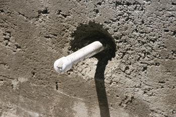 Figure 7
We also set up a system of soaker hoses and an irrigation timer to properly hydrate the concrete as it cures. I know that many builders leave it up to the homeowner to go out and turn the water on and off. As builders, this is our responsibility, not the client's. The hoses and the timer cost about a hundred dollars. Why would you chance improperly cured concrete for such a small price?
Tying Together
As the shell of the pool was nearing completion and being prepped for the tile installation with waterproofing and float material, we turned our attention to the decks and began saw cutting channels for drain lines and electrical conduit. We then went back to tie the sections of the deck together with rebar and epoxy.
We also started setting the deck drain lines and establishing the deck levels with a very slight 100-to-1 inch pitch to ensure proper drainage, and began installing the limestone coping, detailing the Tishways and getting ready for the tile — to be laid in part three of this series.
Next month, in the last of our series on pool construction, we'll cover aesthetic details and some of the landscape elements surrounding the pool.
Comments or thoughts on this article? Please e-mail [email protected].


